Catalog · Institutional specification
5 MW Data Cell & ~6 MW firm Power Cell.
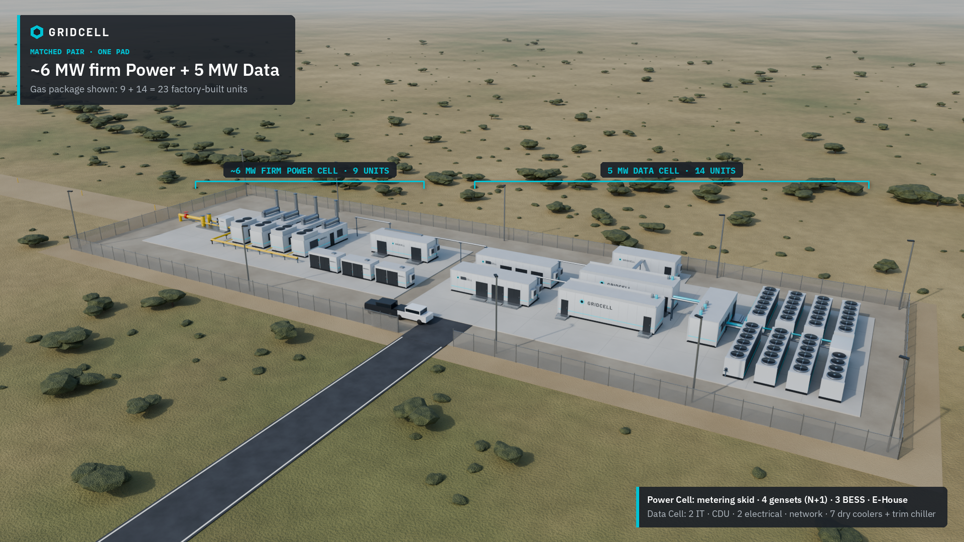
Catalog brick for US AI pads: a 5 MW Data Cell designed for NVIDIA Vera Rubin-class rack-scale systems, and a ~6 MW firm Power Cell (natural gas or power-ready). Units may be ordered paired or standalone. Figures below are indicative design envelopes, not contractual guarantees.
Indicative · Standalone OK · Commercial terms under NDA
No equipment OEM brand names in this public sheet; partner selections are project-driven. NVIDIA Vera Rubin is named only as the hardware platform class the Data Cell is designed for. No partnership or certification is implied.
Matched pair
Why ~6 MW generation for 5 MW IT.
Facility load is not IT nameplate alone. CDU pumps, dry-cooler fans, the trim chiller at peak, electrical losses, and auxiliaries add overhead. With 45 °C warm-water direct-to-chip cooling, peak facility factor is ~1.07–1.16, so ~6 MW firm on the facility bus covers one 5 MW Data Cell with margin for hot-day ambient and BESS recharge.
N+1 gas (3+1 gensets) keeps that ~6 MW continuous with one genset offline. The grid-forming BESS (≥~6 MW PCS, 1–2 h default) carries fast AI load swings and bridges starts. It does not replace continuous megawatts.
Unit A · Data Cell
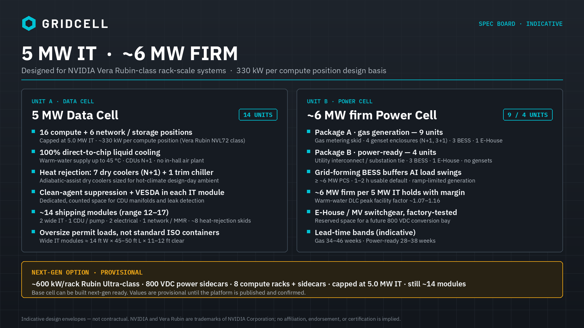
5 MW Data Cell — Vera Rubin-class design basis
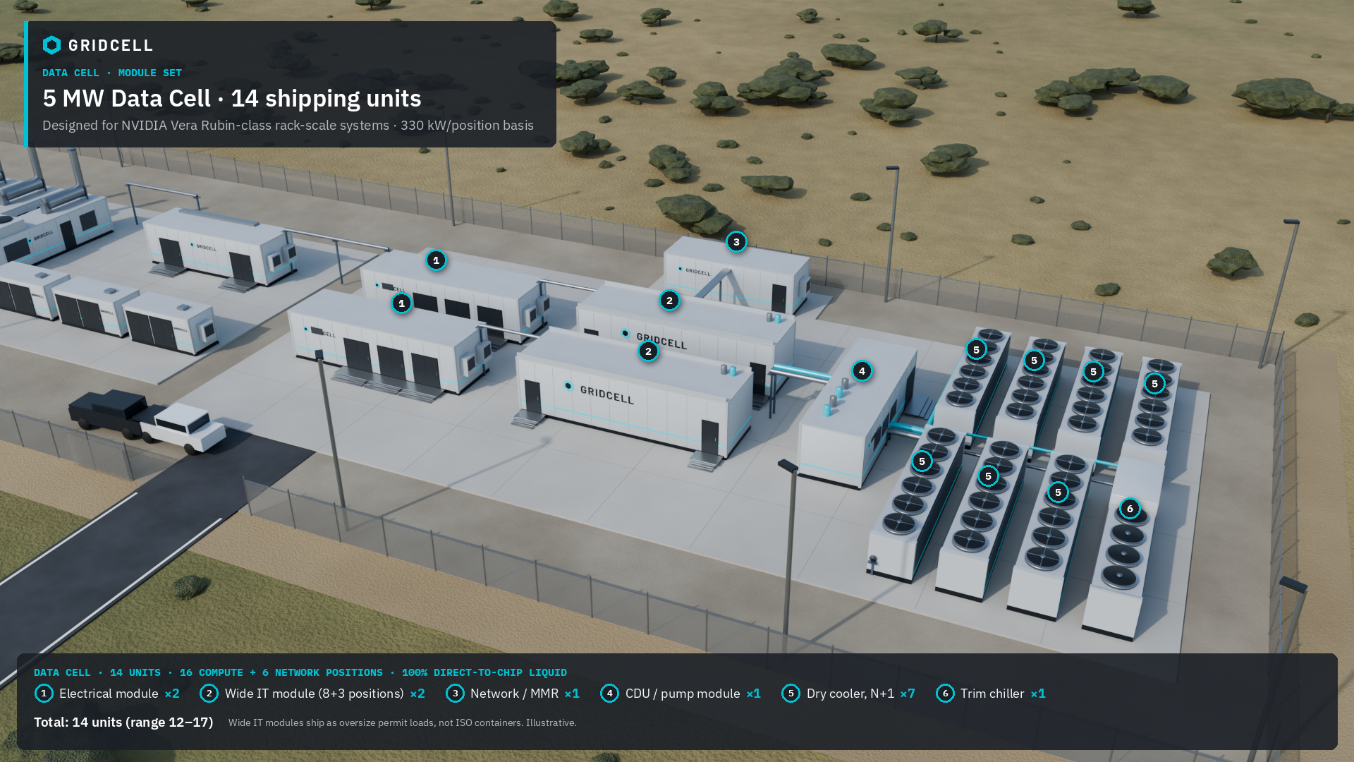
Standard buyable 5 MW IT cell, delivered as about 14 factory-built modules. Scale campuses as multiples of 5 MW IT by landing additional cells.
| Catalog SKU | 5 MW Data Cell — designed for NVIDIA Vera Rubin-class rack-scale systems (Vera Rubin NVL72 class) |
|---|---|
| IT rating | Capped at 5.0 MW IT per cell (enforced by power management) |
| Rack power basis | ~330 kW per compute position (design basis; matches N+1 rack power-shelf capacity, with headroom above published rack TDP) |
| Rack positions | 16 compute + 6 network / storage (22 positions); 8 compute + 3 network per IT module; 8 contiguous compute positions per module |
| Cooling | 100% direct-to-chip liquid; warm-water supply up to 45 °C; CDUs N+1 in a dedicated CDU/pump module; 7 adiabatic dry coolers (N+1) + 1 trim chiller |
| Liquid (indicative) | ~500 L/min (~130 GPM) per 330 kW position at ΔT ≈ 10 K; ~8,000 L/min per cell (calculated; confirmed per rack OEM) |
| Electrical | 2 electrical (LV power block) modules; 415/480 VAC A/B busway per IT module; UPS for CDUs, network, and controls; reserved 800 VDC path |
| IT module envelope | ~14 ft W × 45–50 ft L × 11–12 ft clear; steel deck ≥30 kPa in rack zones; dedicated space for manifolds, leak detection, and clean-agent cylinders |
| Safety | Clean-agent total-flooding suppression + VESDA aspirating smoke detection per IT module; zoned leak detection with branch isolation |
| Power interface | Fed from a matched ~6 MW firm Power Cell (gas or power-ready) via a standardized MV/LV interface |
| Scale-out | Multiples of 5 MW IT by adding Data Cells (and matched Power Cells) |
| Delivery | ~14 shipping modules (range 12–17), shipped as oversize permit loads, not standard ISO containers; racks installed on site; field work is foundations, piping, electrical tie-in, commissioning |
Module schedule — one 5 MW Data Cell
| Wide IT modules | 2 — ~14 ft W × 45–50 ft L × 11–12 ft clear; 8 compute + 3 network/storage positions each |
|---|---|
| CDU / pump module | 1 (range 1–2) — N+1 CDUs, filtration, expansion, make-up, controls |
| Electrical modules | 2 (range 2–3) — LV power blocks, busway feeders, UPS for CDUs / network / controls |
| Network / MMR module | 1 (0–1; can merge into an IT module) — spine / aggregation, fiber patching, two diverse carrier entries |
| Heat-rejection skids | 7 + 1 (range 6–9 + 1) — adiabatic-assist dry coolers N+1 plus one trim chiller |
| Total | ≈ 14 shipping units (range 12–17). The Power Cell is separate (9 units gas / 4 units power-ready) |
Next-gen option Provisional
~600 kW/rack · 800 VDC · same 5 MW cell
For the next Rubin Ultra-class generation of rack-scale systems. Every value in this table is provisional until the platform is published and confirmed. The base Data Cell can be built next-gen ready.
| Status | Next-gen option / provisional — planning basis only; not a released catalog SKU |
|---|---|
| Rack power basis | ~600 kW per compute rack (Rubin Ultra-class), with an 800 VDC power sidecar per rack |
| Rack positions | 8 compute racks (~4.8 MW) + 8 power sidecars + 4 network positions, capped at 5.0 MW IT through rack-level power capping |
| Cooling | 100% direct-to-chip liquid, up to 45 °C supply; ~900 L/min per rack at ΔT ≈ 10 K; same CDU capacity and heat-rejection plant as the base cell |
| Electrical | 800 VDC via sidecars on the AC busway, or centralized DC conversion in the E-House (later); DC-rated protection |
| Structure | Heavier deck (≥50 kPa in compute zones); clear height ≥11 ft |
| Module set | ≈ 14 shipping modules (range 12–18), about the same as the base cell, because total heat and power do not change |
| Next-gen ready base cell | Optional provisions at base build: rack-pair layout, larger headers and branch valves, heavier deck, replaceable busway tap-offs, 800 VDC bay and DC pathway, lithium-ion detection and venting |
Unit B · Power Cell
~6 MW firm Power Cell
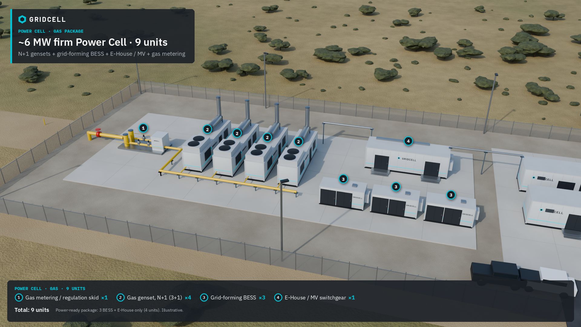
Firm facility bus sized for one 5 MW Data Cell, as a gas package (9 units) or a power-ready package (4 units).
| Catalog SKU | ~6 MW firm Power Cell — natural gas (Package A) or power-ready (Package B) |
|---|---|
| Firm output | ~6 MW firm on the facility bus per 5 MW IT; warm-water DLC peak facility factor ~1.07–1.16 leaves margin for hot-day ambient and BESS recharge |
| Package A · gas (9 units) | 1 gas metering / regulation skid · 4 genset enclosures (N+1, 3+1) · 3 BESS enclosures · 1 E-House / MV switchgear |
| Package B · power-ready (4 units) | Utility interconnect / substation tie (utility or site scope) · 3 BESS enclosures · 1 E-House / MV switchgear · no gensets |
| Generation · N+1 | Package A: pipeline natural gas (city gate or lateral); 60 Hz reciprocating gensets, 3+1 at ~2.0–2.5 MWe class, so ~6 MW continuous remains with one unit offline |
| BESS (default) | Grid-forming, ≥~6 MW PCS on the facility bus; 1–2 h usable (~6–12 MWh class). Carries rack-scale AI load swings (target: full Data Cell step within ~100 ms) while gensets run ramp-limited. ~4 h only if island / tariff products require it |
| Electrical BOP | Factory E-House / MV switchgear → Data Cell electrical modules (indicative 11–34.5 kV MV class; site-locked); reserved 800 VDC conversion bay |
| Redundancy philosophy | N+1 at genset level for firm continuous MW; the BESS covers sub-second to minutes and does not substitute for missing continuous capacity |
| Fire / life safety | BESS to UL 9540 with UL 9540A test data and NFPA 855 siting; gensets and fuel gas per NFPA 37 / 54 |
| Scale-out | One Power Cell per 5 MW Data Cell; campuses grow 10 / 15 / 20 MW IT… with matched ~6 MW firm Power Cells |
| Delivery | Factory-integrated generation, storage, and MV modules; FAT before shipment; field work is foundations, gas or utility tie-in, interconnect, commissioning |
Schedule · Indicative
Lead-time notes
Industry / publicly cited ranges—not GridCell commitments. Weeks vary with slot reservation, customization, and logistics.
| GridCell Order planning (locked) | Gas ~34–46 weeks. Power-ready ~28–38 weeks (Data-only follows the power-ready band). Indicative planning bands only, not a contractual guarantee. Final lead times are set in the agreement. |
|---|---|
| Gas gensets (Americas market context) | Industry / publicly cited ranges have historically run ~60–70 weeks and toward ~110 weeks under market pressure. GridCell Order planning uses the shorter locked bands above for indicative scheduling. |
| BESS (containerized / C&I) | Factory cabinets often ~4–8 weeks standard; custom / multi-MWh ~8–16+ weeks; ocean freight often +2–6+ weeks. Distributor tables for 0.5–5 MWh class sometimes ~10–26 weeks. |
| E-House / MV prefab modules | OEM claims of materially shorter delivery/construction/commissioning vs traditional site-built; absolute weeks are project-specific. |
| Data Cell / modular white space | Typically shorter than genset slots; the ~14 Data Cell modules are built in parallel with the Power Cell when ordered together. Prefab modular stacks are sometimes cited at ~6–8 months end-to-end vs conventional 18–24+ months. |
| Planning implication | Treat genset manufacturing slots as critical path. Align ship dates to site pull—early equipment without foundations creates storage risk. |
Commercial
Pricing & payment
Commercial terms under NDA / direct quote. Standalone Power Cell or Data Cell orders are allowed. List prices and detailed payment schedules are not published on this public site.
Contact contact@gridcellai.com for a formal quote. No card payments on this site.
Request a quote for 5 MW Data and/or ~6 MW firm Power Cells (standalone OK). Pricing and payment schedule are provided under NDA.
On the pad
One brick. Add by count.
Public buyable catalog stays on the 5 MW IT grammar. Each 14-module Data Cell lands beside its matched ~6 MW firm Power Cell (9 units gas, or 4 units power-ready). Campuses scale 10 / 15 / 20 MW IT… without alternate catalog ratings.